Choose your country
We work in partnership with many official Kymco dealers around the world.
You can select the country of your choice from the list below, whatever your choice, we can deliver worldwide!
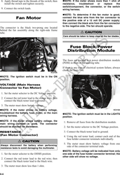
1. Set the meter selector to the DC Voltage position; 3. Install the new speed sensor into the housing with
then disconnect the black/yellow and black pri- new O-ring lightly coated with multi-purpose
mary wires from the coil. grease; then secure the sensor with the cap
screw (threads coated with blue Loctite #242).
2. Connect the red tester lead to the black/yellow Tighten securely.
wire; then connect the black tester lead to the
black wire.
3. Crank the engine over using the electric starter.
4. The meter reading must be within specification.
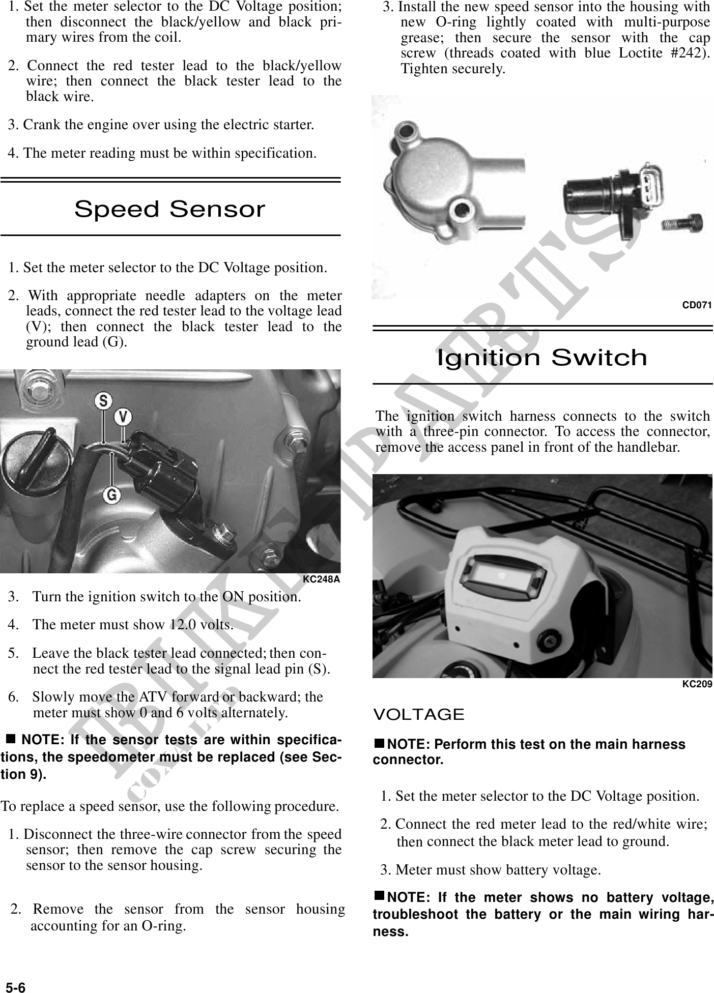
Speed Sensor
1. Set the meter selector to the DC Voltage position.
2. With appropriate needle adapters on the meter
CD071
leads, connect the red tester lead to the voltage lead
(V); then connect the black tester lead to the
ground lead (G).
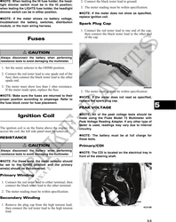
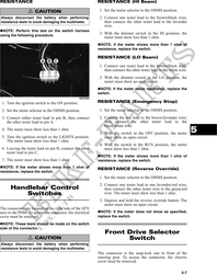
Ignition Switch
The ignition switch harness connects to the switch
with a three-pin connector. To access the connector,
remove the access panel in front of the handlebar.
KC248A
3. Turn the ignition switch to the ON position.
4. The meter must show 12.0 volts.
5. Leave the black tester lead connected; then con-
nect the red tester lead to the signal lead pin (S).
KC209
6. Slowly move the ATV forward or backward; the
meter must show 0 and 6 volts alternately. VOLTAGE
NOTE: If the sensor tests are within specifica- NOTE: Perform this test on the main harness
tions, the speedometer must be replaced (see Sec- connector.
tion 9).
1. Set the meter selector to the DC Voltage position.
To replace a speed sensor, use the following procedure.
2. Connect the red meter lead to the red/white wire;
1. Disconnect the three-wire connector from the speed then connect the black meter lead to ground.
sensor; then remove the cap screw securing the
sensor to the sensor housing. 3. Meter must show battery voltage.
NOTE: If the meter shows no battery voltage,
2. Remove the sensor from the sensor housing troubleshoot the battery or the main wiring har-
accounting for an O-ring. ness.
5-6