Choose your country
We work in partnership with many official Kymco dealers around the world.
You can select the country of your choice from the list below, whatever your choice, we can deliver worldwide!
NOTE: Resistance tests should be made with the VOLTAGE
connector disconnected and on the selector-side
of the connector. 1. Select the 2WD position on the front drive selector
switch; then disconnect the connector on the actu-
RESISTANCE ator wiring harness.
2. With the ignition switch in the OFF position, con-
! CAUTION nect the black tester lead to the black wire in the
Always disconnect the battery when performing supply harness; then connect the red tester lead to
resistance tests to avoid damaging the multimeter. the brown/lavender wire in the supply harness.
3. Turn the ignition switch to the ON position. The
1. Set the meter selector to the OHMS position. meter must show 12 DC volts.
2. Connect the one tester lead to the brown/lavender 4. Connect the red tester lead to the white/blue wire
wire; then connect the other tester lead to the in the supply harness. The meter must show 12 DC
white/lavender wire. volts.
3. With the selector switch in the 2WD position, the 5. Select the 4WD position on the front drive selector
meter must show less than 1 ohm. switch; then connect the red tester lead to the
white/blue wire in the supply harness. The meter
4. With the selector switch in the 4WD position, the must show 0 DC volts.
meter must show an open circuit.
NOTE: The 4WD icon on the LCD should illumi-
NOTE: If the meter does not show as specified,
nate.
replace the front drive selector switch.
6. Connect the red tester lead to the brown/lavender
VOLTAGE wire in the supply harness. The meter must show
12 DC volts.
NOTE: The battery must be connected when per-
forming voltage tests. NOTE: If the voltage readings are as specified
and the actuator does not function correctly,
1. Set the meter selector to the DC Voltage position. replace the actuator (see Section 6).
2. Connect the black tester lead to the negative bat-
tery terminal.
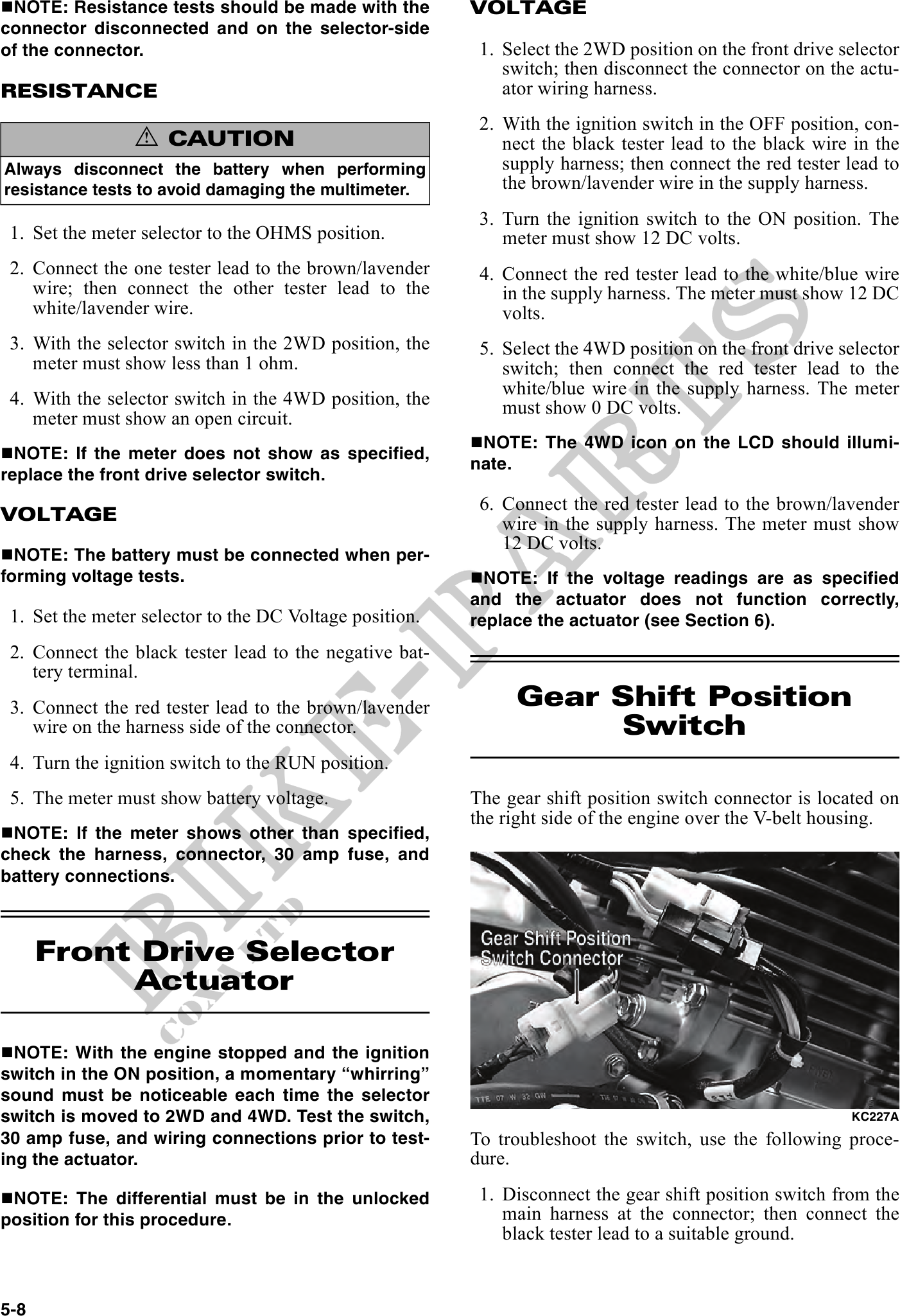
3. Connect the red tester lead to the brown/lavender Gear Shift Position
wire on the harness side of the connector. Switch
4. Turn the ignition switch to the RUN position.
5. The meter must show battery voltage. The gear shift position switch connector is located on
the right side of the engine over the V-belt housing.
NOTE: If the meter shows other than specified,
check the harness, connector, 30 amp fuse, and
battery connections.
Front Drive Selector
Actuator
NOTE: With the engine stopped and the ignition
switch in the ON position, a momentary "whirring"
sound must be noticeable each time the selector
switch is moved to 2WD and 4WD. Test the switch, KC227A
30 amp fuse, and wiring connections prior to test- To troubleshoot the switch, use the following proce-
ing the actuator. dure.
NOTE: The differential must be in the unlocked 1. Disconnect the gear shift position switch from the
position for this procedure. main harness at the connector; then connect the
black tester lead to a suitable ground.
5-8