Choose your country
We work in partnership with many official Kymco dealers around the world.
You can select the country of your choice from the list below, whatever your choice, we can deliver worldwide!
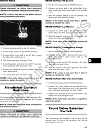
2. Select the OHMS position on the tester and con- RESISTANCE (Charging Coil)
nect the red tester lead to the lavender/red wire;
then move the gear shift lever to the R (reverse) CAUTION
position. The meter must read less than 1 ohm.
3. Move the red tester lead and shift lever in turn to Always disconnect the battery when performing
the light green/red wire and N (neutral) position, resistance tests to avoid damaging the multimeter.
white/black wire and H (high) position, and
white/red wire and L (low) position. The meter 1. Set the meter selector to OHMS position.
must read less then 1 ohm in all positions. If not, 2. Test between the three yellow wires for a total of
the gear shift linkage must be adjusted (see Sec- three tests.
tion 2) or the switch must be replaced. 3. The meter reading must be within specification.
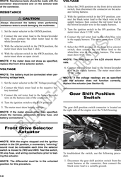
RESISTANCE (Trigger Coil)
Stator Coil
CAUTION
Always disconnect the battery when performing
VOLTAGE resistance tests to avoid damaging the multimeter.
(AC Generator - Regulated Output)
1. Disconnect the gray four-pin connector on the right
1. Set the meter selector to the DC Voltage position. side of the engine just above the starter motor.
2. Connect the red tester lead to the positive battery 2. Set the meter selector to the OHMS position.
post; then connect the black tester lead to the nega- 3. Connect the red tester lead to the green/white
tive battery post. wire; then connect the black tester lead to the
3. With the engine running at a constant 3000 RPM blue/yellow wire. The meter reading must be
(with the headlights on), the meter must show 14- within specification.
15.5 DC volts.
PEAK VOLTAGE
CAUTION NOTE: All of the peak voltage tests should be
made using the Fluke Model 73 Multimeter with
Do not run the engine at high RPM for more than
10 seconds.
Peak Voltage Reading Adapter. If any other type of
tester is used, readings may vary due to internal
NOTE: If voltage is lower than specified, test circuitry.
charging coil - no load.
NOTE: The battery must be at full charge for
VOLTAGE (Charging Coil - No these tests.
Load)
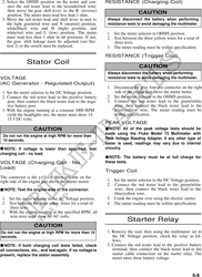
Trigger Coil
The connector is the y e l l o w three-pin one on the
right side of the engine just above the starter motor. 1. Set the meter selector to the DC Voltage position.
2. Connect the red tester lead to the green/white
NOTE: Test the engine-side of the connector. wire; then connect the black tester lead to the
blue/yellow wire.
1. Set the meter selector to the AC Voltage position. 3. Crank the engine over using the electric starter.
2. Test between the three yellow wires for a total of 4. The meter reading must be within specification.
three tests.
3. With the engine running at the specified RPM, all
wire tests must show 60 AC volts.
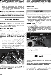
Starter Relay
CAUTION
Do not run the engine at high RPM for more than 10 1. Remove the seat; then using the multimeter set to
seconds. the DC Voltage position, check the relay as fol-
lows.
NOTE: If both charging coil tests failed, check 2. Connect the red tester lead to the positive battery
all connections, etc., and test again. If no voltage is terminal; then connect the black tester lead to the
present, replace the stator assembly. starter cable connection on the starter relay. The
meter must show battery voltage.
5-9